Hacking cheap WiFi LED Controller (BL602)
Some background story
It’s been actually a long time since I bought the controller about which I will talk in this blog post. I use an IKEA SANNAHED frame to display my old Game Boy with Tetris and pimped that with some LED lights. In order to control these through my Home Assistant setup I bought a really cheap controller with WiFi support on Amazon. Sadly the App and WiFi setup was not as stable as I wished and the device lost it’s connection (and needed a full reset ._.) so often that I got really frustrated. About two years later and my movement towards hardware hacking I thought about having a look into it.
The first steps
 The cheap controller I bought
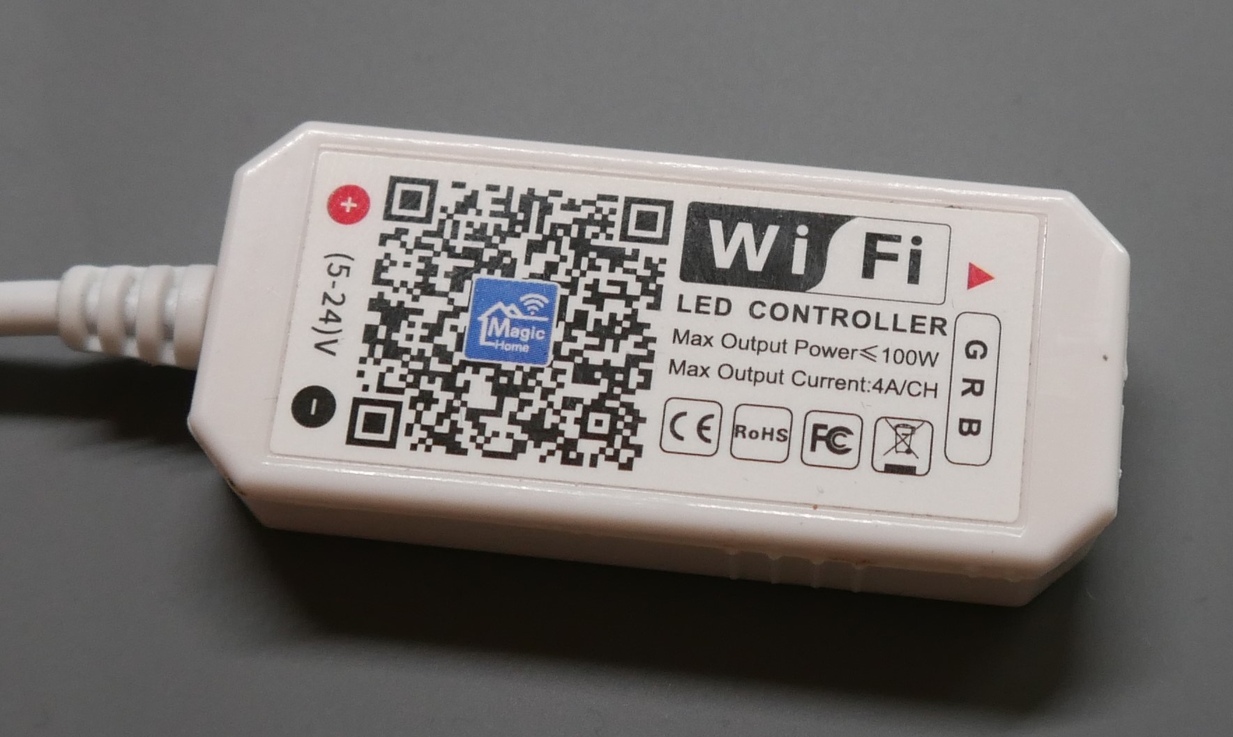
The first step was obviously to inspect the controller I actually bought. And well… there was not that much to inspect. A WiFi logo, the input voltage, some power ratings, a guide on how to correctly plug in the LED strip and probably fake certificates. Additionally there is the big QR-Code for the “Magic Home” App to control this thing. We need a deeper look…
 Back of the controller board
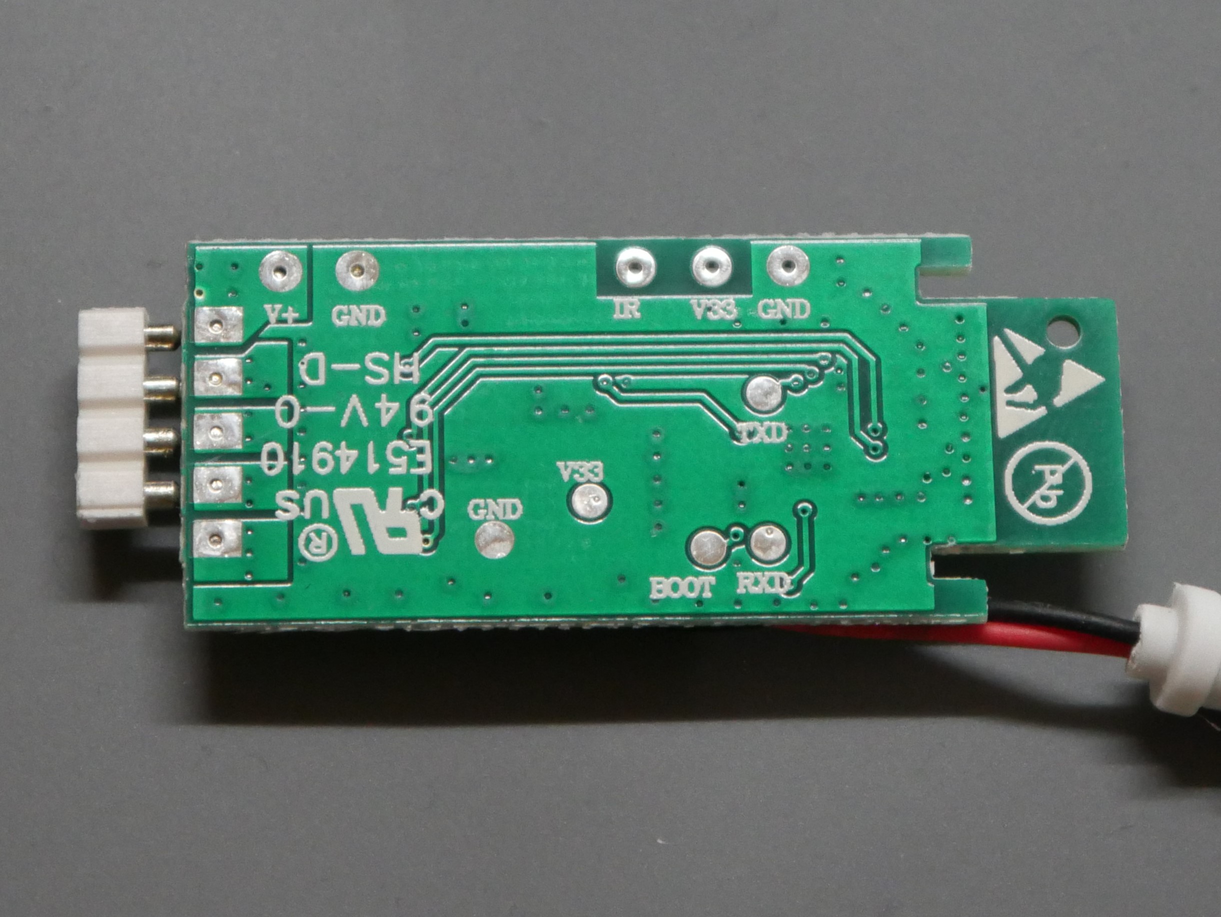
After removing the plastic housing, which was done quite easily with a screwdriver as the housing was just held with some slips together, I could see the back of the controller board. Without even looking at the electronics they used I can already spot some interesting solder pads. BOOT, TXD and RXD together with Ground and 3.3V. These looked very promising for maybe flashing the main controller on the board? (fOrEsHaDoWiNg?)
 Front of the controller board
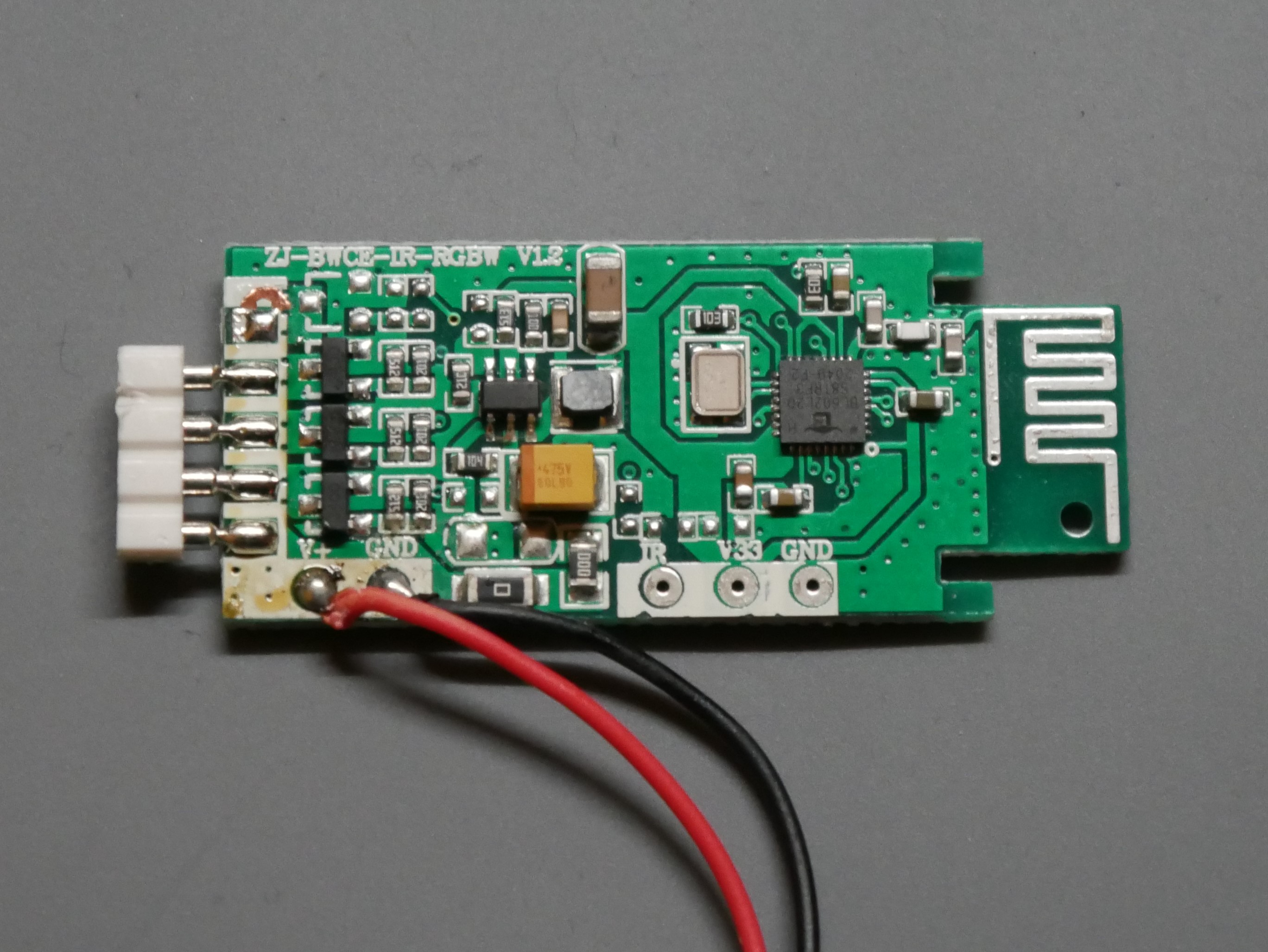
After turning the board around I could finally see the electronics. Pretty simple I would say: Some power management, switching stuff for the LEDs, a PCB antenna and the main control IC. Let’s have a closer look at it.
 Main control IC
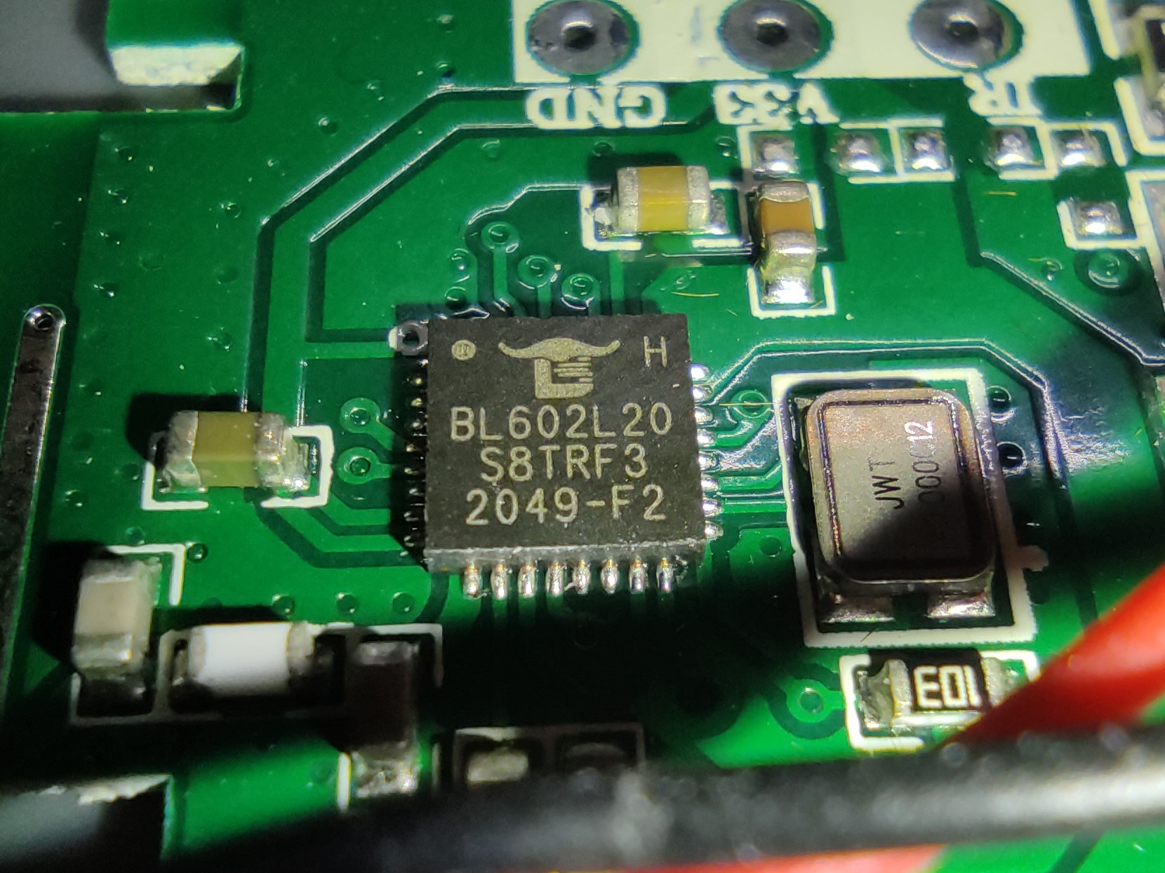
Thanks to modern smartphones with a bazillion cameras on it I could take a macro picture of the IC to have a look at the markings. This seemed to be a BL602L20. A quick search for “BL602L20 Datasheet” in a search engine of your choice and you will find out that this is actually a BL602 from Bouffalo Lab. Why Bouffalo and not Buffalo? I have no idea. Anyways, on the website of the manufacturer is quite some information about this chip. It actually got a 32-bit RISC-V Processor in it, some WiFi and Bluetooth stuff and even support for Secure Boot and a dedicated encryption engine for AES. I’m impressed O_o. The datasheet is also publicly available through a really sketchy HTTP-Only website (here) This finally gives clarity about the marking on the chip.
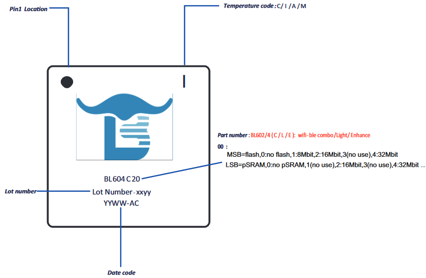 Explanation of the markings on the chip
The chip in my controller has the following specifications:
- Model: BL602
- Features: Light (Whatever that means, maybe only 2.4GHz and not 5GHz?)
- Flash: 16 Mbit (2 MB)
- pSRAM: None
When searching for “BL602L20” another entry hit my eye. There seems to be quite a big community around these kinds of controllers as there was a forum entry on elektroda.com about this exact chip and slightly different controller board. It explains pretty well how to flash an open source firmware to this thing which includes MQTT support for Home Assistant. Why trying to invent something new if there already exists the solution? The is a huge database of devices that can be used with this firmware. Just have a look here.
What’s next?
In order to flash the firmware to the device I had to connect it through the already mentioned solder pads to my PC. So the next step was to obviously put some solder on the pads and solder jumper wire to all of these.
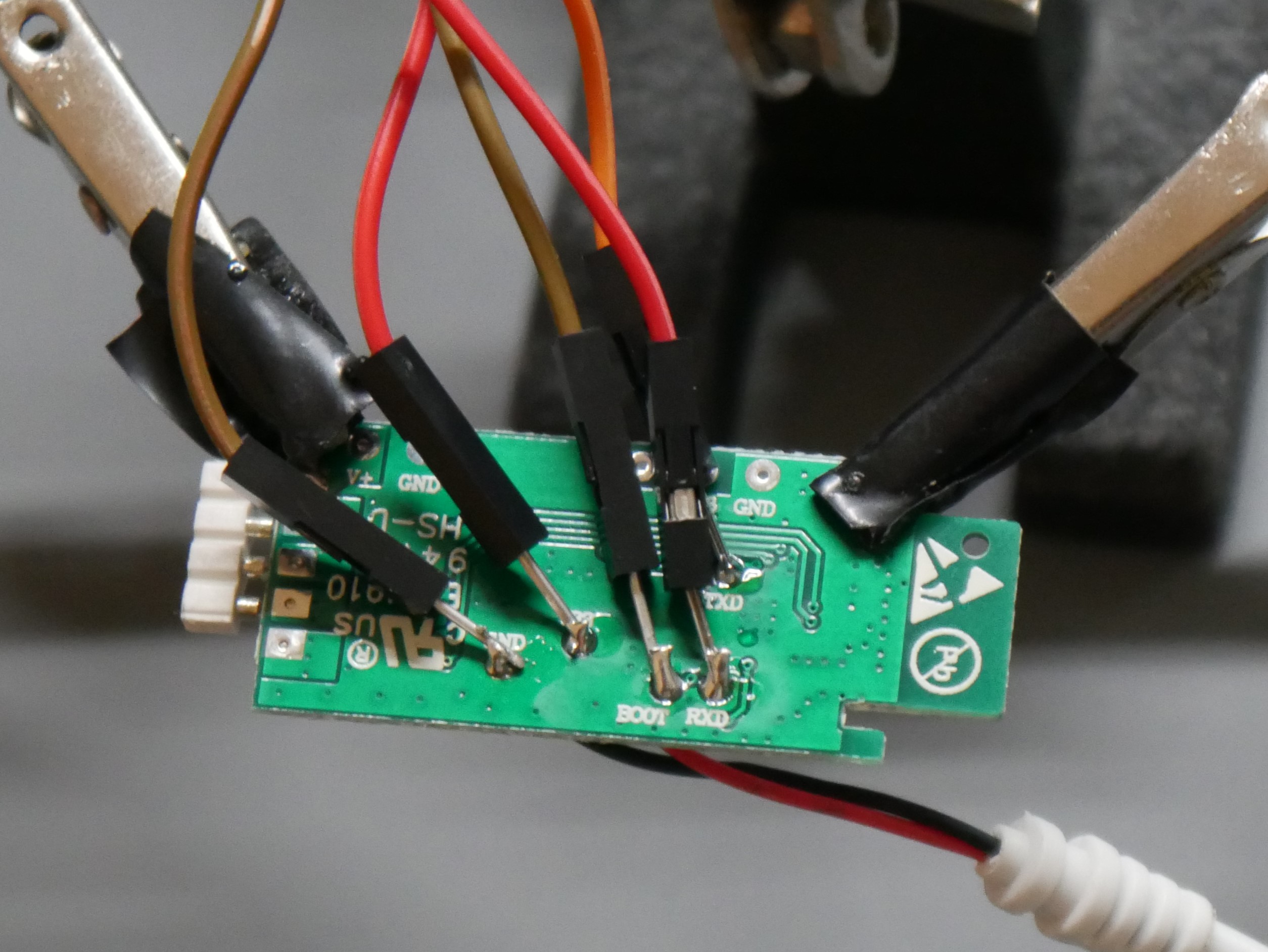 Wires soldered to the pads
The article on the forum mentioned that RXD and TXD must be connected to “TTL”, so I assumed this is just a UART communication. Because I was curious I wanted to connect it without a 10K Ohm resistor between BOOT and V33, which is necessary to place the chip into programming mode. But dammit, I don’t have a UART to USB Adapter, so what to do? I used my Arduino UNO in the past as an alternative. Just remove the ATMEL Chip on the board or connect RESET to Ground and boom, UART Adapter on the Pins TX and RX. While this worked without a problem in this step, the flashing later did not. I spend hours trying to find a workaround because I didn’t want to wait until my ordered UART adapter arrives. The solution? A Raspberry Pi! On the 20-Pin header are some RX and TX Pins that can be used for serial communication! Hurray!
After connecting everything up and starting minicom, a serial terminal, we could finally see some output. And boy was this a lot of output. The entire boot sequence and a huge amount of debugging messages flew in my eyes. To get to this point I had to find the correct baud rate for the communication. Turned out that it uses a very high value of 2 000 000.
Flashing a firmware
Now that I knew the connection was working I connected everything properly for the flashing process.
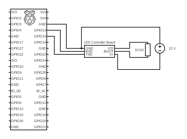 Connection diagram
I powered the controller board through the 12V power supply I would use for normal operation and just connected TXD, RXD and GND to the Pi. This time I also used the mentioned 10K Ohm resistor to place the chip into programming mode.
Because I was now on a linux OS and not windows like the article I followed I had to came up with a different plan. The article uses a Windows GUI application for the flashing process but after some searching I found that there was a command line tool in python available too: “bflb-iot-tool”. This could easily be installed through pip.
1
$ pip install bflb-iot-tool
To flash the firmware I basically looked at the help output of the cli tool and the screenshots provided by the article to set the correct parameters. My final call then looked like this:
1
$ bflb-iot-tool  --chipname bl602 --port /dev/ttyAMA0 --boot2 chips/bl602/builtin_imgs/boot2_isp_bl602_v6.6.1/boot2_isp_release.bin --pt chips/bl602/partition/partition_cfg_2M.toml --firmware OpenBL602_1.17.734.bin
- chipname: Model of the chip
- port: Serial port to use
- boot2: I guess the bootloader, can be found by downloading the Windows GUI application in the mentioned path
- pt: Partition table, has to match the flash size, can also be found in the Windows application
- firmware: The actual firmware to flash. Got mine from the official GitHub Repo
With crossed fingers and a bit of patience the flashing process was successful ^^
I unplugged the resistor and booted the controller. Finally I saw the open WiFi Network “OpenBL602_[…]” and immediately connected to it. When the connection was made I could visit http://192.168.169.1 to open the web interface and put in my own home WiFi credentials. A quick reboot and a look into my routers known devices and I had the new IP of the device which was now connected to my WiFi instead of creating the access point. Now it was just a matter of further configuring the controller and connecting it to my MQTT broker. I wont go into details here and highly recommend to just play around with the settings, you will learn a lot!
Final thoughts
I’m really happy that I took a look into this again. It was a fun little project and I can highly recommend trying it on your own! There is also a great YouTube channel from Elektroda itself with how-to videos: https://www.youtube.com/@elektrodacom
If you got any questions just write a comment and I will try to help!
 Final result
See u next time
Christian