Digispark with Arduino IDE in 2024
What is a “Digispark”?
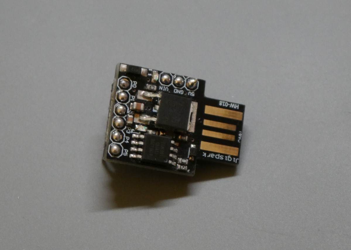
I bought a 3 pack of Digispark microcontrollers back when I was heavily into ordering Arduino-Stuff for way to much money on Amazon. But these things are actually quite nice. They are based around the ATTiny85, feature six GPIOs, work with 5V and do have a voltage regulator onboard which allows them to accept anything between 6V and 16V as an input. Additionally the board is shaped in a way, that it can directly be plugged into a USB-Port. Also there are libraries from the company itself that allows it to present itself as pretty much any USB device you want. Thats a lot of features for a board about the size of a coin.
Problem #1 – How to program?
As nice as this thing is, using it in 2024 is not so easy. The original manufacturer, DigiStump, seems to be out of business by now. Meaning the Website is down and the GitHub repos got updated about 7 years ago. So getting this thing to work inside the Arduino IDE is not so simple because how would you get the Digispark into the Board Manager if the website with the corresponding packages is down? Luckily there are some awesome people that took development in their own hands. So there exists a newer version of the boards for the Arduino IDE from ArminJo.
Installation for Arduino IDE
To get the Digispark working in the Arduino IDE you simply need to setup the following URL as a “Additional boards manager URL” in the preferences of the application.
https://raw.githubusercontent.com/ArminJo/DigistumpArduino/master/package_digistump_index.json
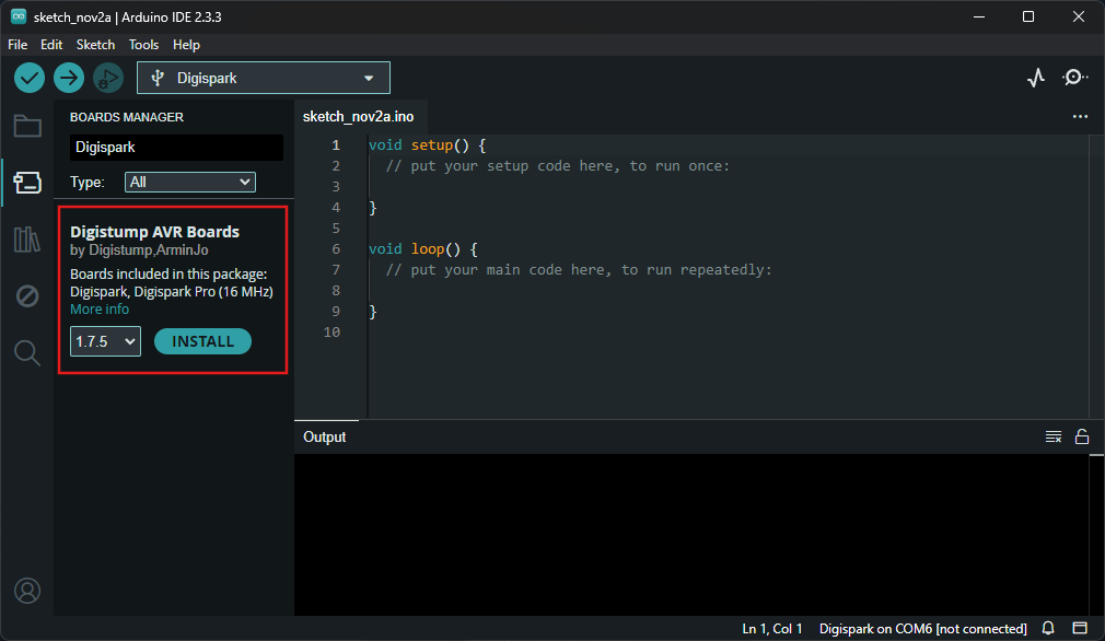
After you added the URL there, the IDE will list the “Digistump AVR Boards” in the board manager. After you click install, all the data needed for the Digispark will get installed, including necessary drivers, which is pretty neat.
 Installation inside the Arduino IDE
Before you upload any sketch, it is recommended to update the bootloader of the Digispark. You can think of it as a miniature program that gets loaded before any code you put on it. It handles the execution of you code and in this case the programming via the USB-Port. To do that, just follow these steps:
- Click on “Tools”
- Select “Digispark” as your Board
- Select “Upgrade (via USB)” as “Burn Bootloader Method”
- Set the “Clock” to “16.5 MHz - For V-USB” if you want to use the USB functionality of the Digispark
- Select as a Programmer “micronucleus2.5”
- Finally click “Burn Bootloader”
After that the tool will ask you to plug in the Digispark, if its already plugged in, you may have to remove it and then plug it back into your PC.
Now you can do whatever you want to do with your updated Digispark. There are quite a lot of examples included for various tasks, including examples for Keyboard, Mouse and Joystick emulation.
Problem #2 – Why is it resetting?
Sadly not everything is working as expected. If you bought your Digispark not from the original manufacturer there is a high chance, that pin P5 is resetting the microcontroller if it’s pulled low. That’s because this pin is connected to the reset pin of the ATTiny85. The original manufacturer already disabled the reset function of the ATTiny so it can be used as a normal GPIO but for some reason (maybe money money money) that is not the case for the cheap clones. Combine that with the Pins P3 and P4 which are connected to the USB data pins and you are left with only three pins if you want to use the USB functionality. Thats not a lot. And because the analog pins are P2 - P5, and we cannot use P3, P4 and P5 we are left with a single analog input. So what can we do?
Disable the RESET Pin
Obviously if Digistump could deactivate the reset function, we can do that too! But we do need some additional hardware. Thankfully an Arduino UNO or similar is enough. To deactivate the RESET function we need to set the correct fuses inside the ATTiny.
IMPORTANT: After setting the fuses, the Digispark can ONLY be programmed through the USB-Port which is handled by the bootloader. If this ever fails and you need to do the ISP programming again, you will need a “high voltage programmer” to reset the fuses.
Connect Arduino
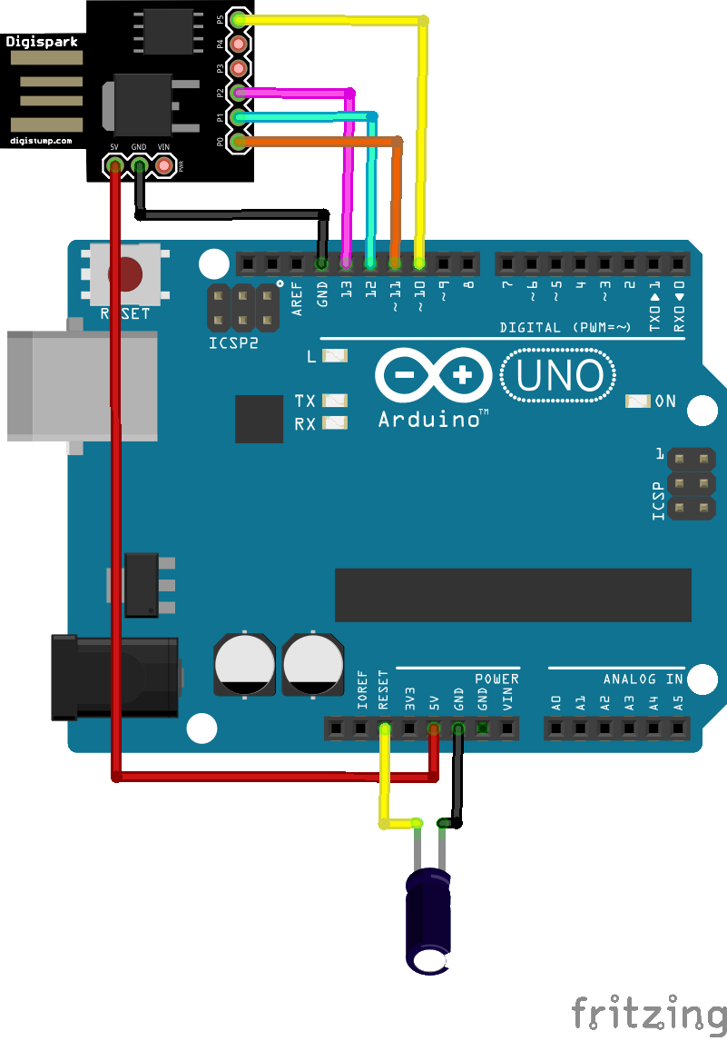
This can be done by using the ISP programming interface of the ATTiny, basically we need to connect some pins to the Arduino as shown in the picture.
 Connection with Arduino UNO for ISP programming
The Capacitor between RESET and GND of the Arduino UNO is highly recommended, I had no issues when not connecting it.
Install WinAVR
The first step is now to setup the Arduino UNO to act as an ISP programmer, for that you can install the “ArduinoISP” sketch you will find in the examples of the Arduino IDE. After that you need the “WinAVR” tools in order to interact with the ATTiny of the Digispark through the Arduino. You can download this here: https://sourceforge.net/projects/winavr/
Disable RESET
To check if everything is working properly you can now run the following command, replacing the COM-Port with the Port your Arduino UNO is connected to.
1
> avrdude -P COM6 -b 19200 -c avrisp -p attiny85 -n
The output should say avrdude: safemode: Fuses OK. If not, please check your connections. If everything looks good, then you can set the fuses to disable the reset functionality:
1
> avrdude -P COM6 -b 19200 -p attiny85 -c avrisp  -U hfuse:w:0x5F:m
Again, the output should say avrdude: safemode: Fuses OK. If so, congratulations, you can now use the pin P5 as a normal GPIO.
Problem #3 – Oops, need the ISP programming back
After you disabled the reset functionality, you cannot use the same method to enabled it again because for that, you actually need the reset functionality. So what can we do?
High voltage programming
There is a way to set the fuses even in this state. It’s called High voltage programming. Don’t be scared, “High voltage” means just 12V.
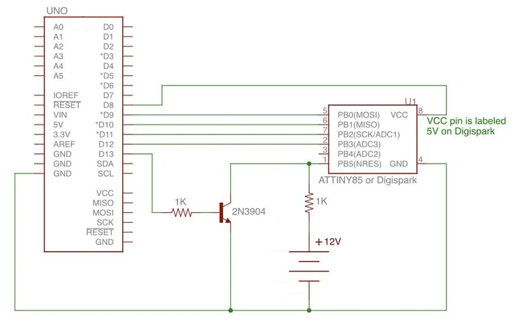
To do that I can highly recommend this Github repo: https://github.com/psitech/Arduino-based-HV-programmer-for-Digispark-ATtiny85 You can simply wire the Arduino UNO and a 12V power supply up like the following schematic and program the provided Sketch onto the Arduino. After opening the Serial Monitor and sending over any key, the fuses get set to their default state. Please note that the 5V pin of the Digispark is connected to Pin 8 of the Arduino UNO. When you connect the Pin directly to the 5V Pin of the UNO, it will not work.
 Connection with Arduino UNO for high voltage programming
You don’t need the exact same transistor shown in the schematic. A similar NPN transistor will work fine. I used the S8050 cause I had it laying around. Just make sure it can handle 12V.
Final thoughts
It is still simple to use the Digispark with the Arduino environment, if you know where to look. Finding the correct libraries and boards for the IDE took me a long time. Also information about the High voltage programming is not so easy to find on the internet. That’s why I made this post so I can maybe combine the information I found scattered around in one place. I have to give huge credits to (https://wolles-elektronikkiste.de)[https://wolles-elektronikkiste.de]. It’s a german site but helped me a lot trying to get the ISP programming working. If you know german, have a look there, amazing content!
As always, if you got any questions just write a comment and I will try to help!
See u next time
Christian

